
 Deutsch
  Español
  Français
  Italiano
  Português
  Svenska
  Suomi
Suomi  Dansk
Dansk  Norsk bokmål
  Nederlands
  العربية
  עברית
עברית  Polski
  Türkçe
  Русский
  Uzbek
Uzbek  Azərbaycan
  Tiếng Việt
  ไทย
ไทย  한국어
한국어  日本語
日本語  简体中文
简体中文 
In the landscape of EV infrastructure and power electronics, the bridge rectifier is a fundamental component. Whether integrated into a high-performance DC charging station or a compact residential AC wallbox, its role is critical: converting alternating current (AC) from the grid into the stable direct current (DC) required by sensitive power modules.
For maintenance engineers, hardware developers, and quality control specialists, knowing how to verify the integrity of a bridge rectifier is essential. A faulty rectifier can lead to catastrophic power failure, efficiency loss, or damage to downstream components. This guide provides a professional, step-by-step methodology for testing a bridge rectifier using a digital multimeter (DMM).
Understanding Bridge Rectifier Architecture
Before testing, it is vital to understand the internal configuration. A standard single-phase bridge rectifier consists of four diodes arranged in a specific bridge configuration.
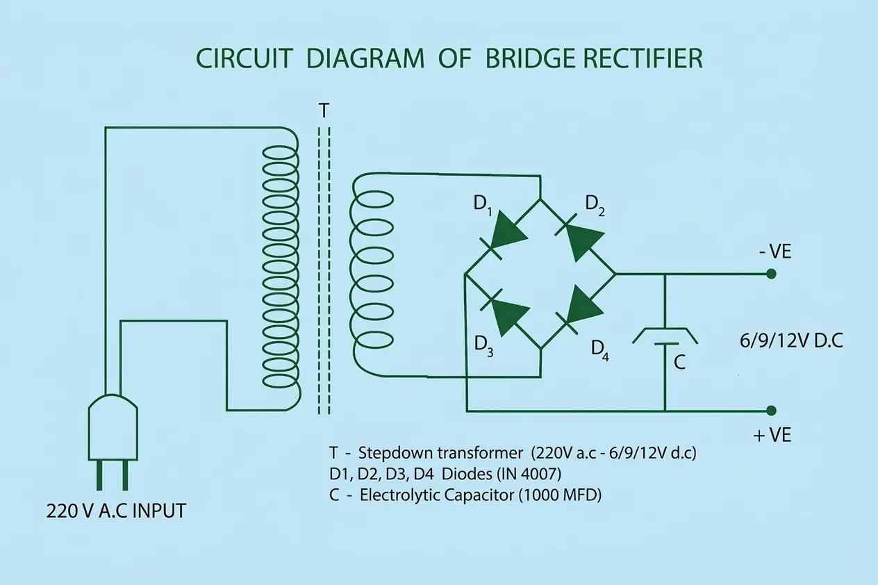
The component typically features four terminals:
- AC Input (~): Two terminals where the alternating current enters.
- Positive DC Output (+): Where the rectified positive voltage exits.
- Negative DC Output (-): The return path for the DC circuit.
At PandaExo, we leverage our deep heritage in power semiconductors to ensure that every bridge rectifier integrated into our charging solutions meets rigorous thermal and electrical tolerances.
Essential Tools and Safety Precautions
To perform a valid test, you will need:
- A Digital Multimeter (DMM) with a “Diode Test” mode.
- The component’s datasheet (to verify pinout and forward voltage V_f specs).
Safety Warning: Ensure the power source is completely disconnected. If the rectifier is part of a larger circuit, such as an EV charger power board, ensure all high-voltage capacitors are fully discharged before proceeding.
Step-by-Step Testing Procedure
The goal of this test is to verify that each of the four internal diodes allows current to flow in only one direction and exhibits the correct forward voltage drop.
1. Set Your Multimeter
Turn your multimeter dial to the Diode Test mode (usually symbolized by a diode icon). This mode sends a small current through the diode to measure the voltage drop.
2. Testing the Positive Side (Positive Terminal to AC Terminals)
- Step A: Place the Black (Negative) probe on the Positive (+) terminal of the rectifier.
- Step B: Touch the Red (Positive) probe to each of the AC (~) terminals one by one.
- Expected Result: You should see a reading between 0.5V and 0.8V (for standard silicon diodes). This indicates the diodes are forward-biased and healthy.
- Step C: Reverse the probes (Red on Positive, Black on AC).
- Expected Result: The multimeter should show “OL” (Open Loop). This confirms the diodes are successfully blocking reverse current.
3. Testing the Negative Side (Negative Terminal to AC Terminals)
- Step A: Place the Red (Positive) probe on the Negative (-) terminal of the rectifier.
- Step B: Touch the Black (Negative) probe to each of the AC (~) terminals.
- Expected Result: Again, you should see a reading of 0.5V to 0.8V.
- Step C: Reverse the probes.
- Expected Result: The multimeter should show “OL”.
Interpreting the Results
A bridge rectifier is considered functional only if all four internal diodes pass both the forward and reverse bias tests.
| Multimeter Reading | Diagnostic Status | Action Required |
|---|---|---|
| 0.5V – 0.8V | Healthy Silicon Diode | None; component is functional. |
| 0.000V or Continuity Beep | Short Circuit | Replace Immediately; high risk of fire/damage. |
| “OL” in both directions | Open Circuit (Blown) | Replace Immediately; circuit will not complete. |
| 0.1V – 0.3V | Potential Leakage/Heat Damage | Monitor or replace for critical EV chargers. |
Technical Note: In high-power applications, such as DC Fast Charging, bridge rectifiers are subject to significant thermal stress. Even if a rectifier passes a “cold” multimeter test, it may still fail under high-load thermal conditions if the internal semiconductor structure is degraded.
Why Quality Rectification Matters in EV Infrastructure
In the EV industry, the bridge rectifier is the “gatekeeper” of power. PandaExo’s manufacturing philosophy prioritizes industrial-grade power semiconductors because we understand that the reliability of a 240kW DC station depends on the integrity of its core components.
By sourcing factory-direct hardware from a manufacturer with a 28,000-square-meter advanced production base, you ensure that every component—from the bridge rectifier to the smart management software—is engineered for longevity and high efficiency.
Testing a bridge rectifier is a straightforward but vital diagnostic skill for maintaining the integrity of power electronics. By following this systematic approach, you can identify failures early and prevent costly damage to your EV charging infrastructure.
Are you looking to upgrade your network with high-performance, precision-engineered charging solutions? Explore PandaExo’s full range of EV chargers or contact our technical team today for customized OEM/ODM services.


