
 Deutsch
  Español
  Français
  Italiano
  Português
  Svenska
  Suomi
Suomi  Dansk
Dansk  Norsk bokmål
  Nederlands
  العربية
  עברית
עברית  Polski
  Türkçe
  Русский
  Uzbek
Uzbek  Azərbaycan
  Tiếng Việt
  ไทย
ไทย  한국어
한국어  日本語
日本語  简体中文
简体中文 
Rectifier choice looks simple on paper, but in real power-supply design it has direct consequences for heat, filtering cost, reliability, and usable output quality. For engineers building EV charging hardware, industrial supplies, onboard conversion stages, or semiconductor-based power modules, the difference between half-wave and full-wave rectification is not academic. It affects whether the final system is efficient enough, stable enough, and commercially viable enough to scale.
This is why full-wave rectification dominates serious power electronics. Half-wave topologies still matter as a teaching reference and for very low-power circuits, but once current density, thermal control, and output quality become important, the engineering tradeoff becomes clear.
Why Rectifier Topology Matters in Modern Power Systems
The grid supplies alternating current, while batteries, control boards, and most power electronics require direct current. Rectifiers perform that conversion by allowing current to flow in only the required direction.
The topology you choose changes far more than the waveform shape. It also changes how much of the incoming AC energy is actually used, how much ripple remains on the output, how large the filter stage must be, and how much thermal stress the system must handle.
| Design Question | Half-Wave Impact | Full-Wave Impact |
|---|---|---|
| How much of the AC waveform is used | Only one half-cycle is used | Both half-cycles are used |
| How smooth the DC output is | Poorer output smoothness | Cleaner and easier-to-filter output |
| Filter capacitor burden | Higher | Lower |
| Practical suitability for serious power conversion | Limited | Strong |
| Relevance to EV and industrial systems | Rarely suitable | Standard practice |
For anyone working on charger design or power-conversion architecture, PandaExo’s article on AC-to-DC power conversion in commercial EV chargers provides a broader system-level view.
What a Half-Wave Rectifier Actually Does
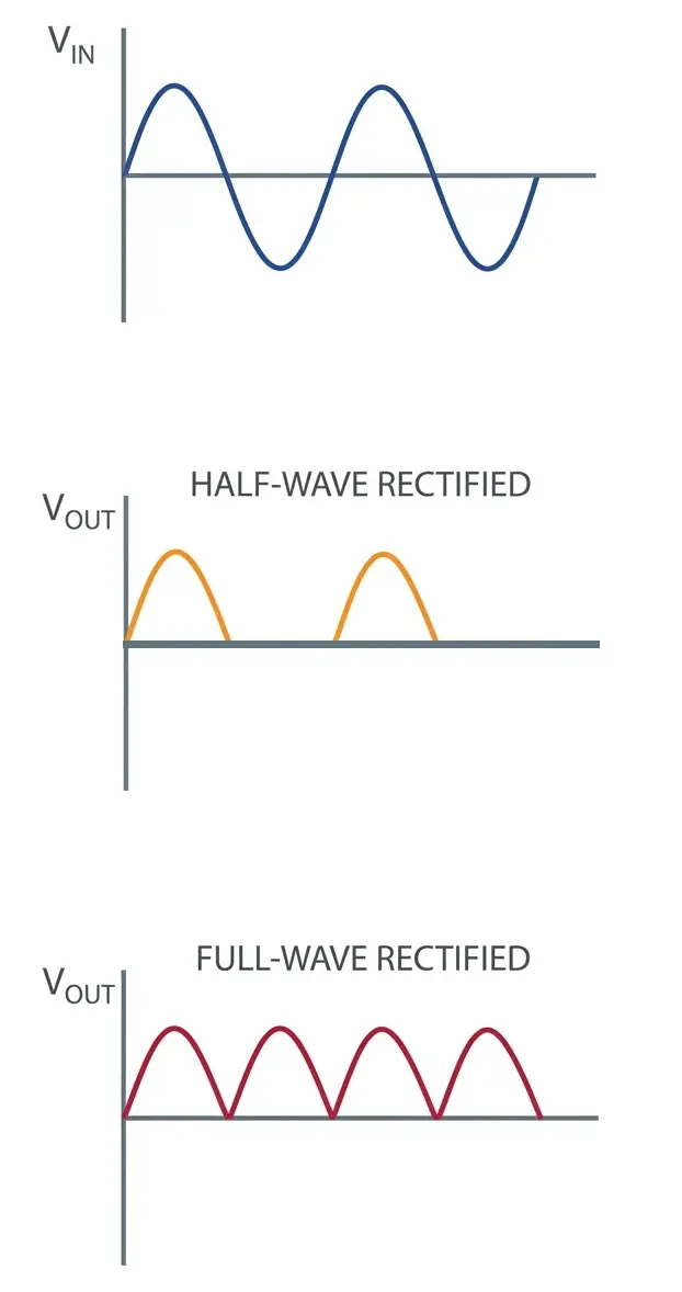
A half-wave rectifier is the simplest AC-to-DC topology. In its most basic form, it uses a single diode in series with the load. During one half of the AC cycle, current passes. During the opposite half, current is blocked.
That simplicity is its main advantage. The problem is that the circuit throws away half of the available waveform. The result is a highly pulsating output with large gaps between conduction periods.
From an engineering standpoint, that creates a poor foundation for any application that depends on stable DC power.
| Half-Wave Characteristic | Engineering Consequence |
|---|---|
| One diode, simple layout | Very low component count and low upfront cost |
| Uses only half the waveform | Lower conversion efficiency and poor transformer utilization |
| Large output gaps | High ripple and larger filtering requirements |
| Narrow conduction window | Greater stress on downstream smoothing components |
| Suitable mainly for simple circuits | Better aligned with low-power or non-critical applications |
In practice, half-wave rectification is best understood as the minimum-case topology, not the preferred one for modern high-performance equipment.
Why Full-Wave Rectification Became the Standard
A full-wave rectifier uses both halves of the AC cycle. That can be achieved with a center-tapped arrangement or, more commonly in modern equipment, a bridge rectifier using four diodes.
By redirecting current so that the load always sees the same polarity, a full-wave design extracts much more useful energy from the input waveform. That one design difference drives a cascade of system-level benefits: higher efficiency, lower ripple, easier filtering, and better suitability for continuous operation.
In real commercial hardware, these benefits are not optional. They are part of what allows chargers and power modules to run reliably under load.
For applications that depend on robust diode bridges, PandaExo’s bridge rectifier components are directly relevant to thermal and electrical design decisions.

Full-Wave vs. Half-Wave: Core Technical Comparison
The comparison below captures the engineering differences that usually drive the decision.
| Parameter | Half-Wave Rectifier | Full-Wave Rectifier |
|---|---|---|
| Diode count in common implementation | 1 | 4 in bridge form |
| Maximum theoretical efficiency | 40.6% | 81.2% |
| Ripple factor | About 1.21 | About 0.48 |
| Output ripple frequency | Same as input frequency | Double the input frequency |
| Transformer utilization | Low | Much higher |
| Filter capacitor requirement | Large | More manageable |
| DC output quality | Poorer and more pulsating | Smoother and easier to regulate |
| Best-fit applications | Very low-power, cost-sensitive circuits | EV chargers, industrial supplies, inverters, conversion modules |
This is the table that matters to buyers as well as engineers. Higher efficiency means less wasted energy. Lower ripple means less downstream stress. Better utilization means a more credible design for commercial deployment.
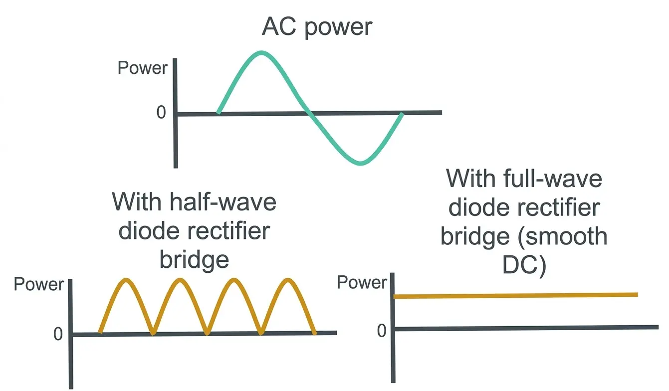
Ripple Is One of the Most Important Practical Differences
Many design teams focus on efficiency first, but ripple is often where the larger system consequences become visible. A half-wave rectifier produces a rougher output waveform, which means the filter stage has to work harder to deliver stable DC. That usually leads to larger capacitors, more heat exposure, and a less elegant power stage.
A full-wave rectifier produces more frequent output pulses, which makes the DC easier to smooth and regulate. That reduces the burden on capacitors and helps the rest of the system operate with less electrical noise and lower thermal stress.
| Ripple-Related Issue | Half-Wave Result | Full-Wave Result |
|---|---|---|
| Output smoothness | Poor | Much better |
| Filtering effort | High | Lower |
| Stress on capacitors | Higher | Lower |
| Suitability for stable downstream electronics | Limited | Strong |
| Fit for demanding charger or inverter environments | Weak | Strong |
For engineers evaluating downstream reliability, this point connects directly to PandaExo’s article on minimizing ripple voltage in automotive power delivery.
The Thermal and Efficiency Argument Is Decisive
In low-power applications, engineers can sometimes tolerate lower efficiency if the cost target is extremely aggressive. In high-power systems, that argument collapses quickly. Every unnecessary loss becomes heat, and every thermal penalty raises risk across the enclosure.
In EV charging infrastructure, thermal management is already a central design concern. Cables, busbars, switches, capacitors, power modules, and enclosures all operate under sustained electrical and environmental stress. A topology that wastes more energy and produces poorer DC quality makes that job harder.
This is why full-wave rectification is not just preferred in commercial charging systems. It is effectively assumed.
Why Full-Wave Rectification Matters in EV Charging Infrastructure
In AC charging systems, rectification may happen in the vehicle’s onboard charger, where space, thermal limits, and vibration resistance all matter. In DC charging systems, the charging station itself handles large-scale AC-to-DC conversion and must do so with high efficiency and stable output behavior.
In both cases, full-wave rectification is the practical choice because it supports:
- Better energy utilization from the grid
- Lower ripple and easier downstream regulation
- Reduced filtering burden
- Better thermal performance at system level
- A more credible foundation for long-life commercial hardware
The relevance grows further when charging infrastructure must maintain uptime across public sites, fleet depots, retail properties, and distributed charging networks. At that point, topology choice becomes part of lifecycle cost, not just circuit theory.

When Half-Wave Still Makes Sense
Half-wave rectifiers are not useless. They still have a place in simple, low-cost, low-current designs where output quality is not critical and efficiency is not the primary constraint.
That usually means:
- Basic signal or detector circuits
- Very low-power adapters
- Educational demonstrations
- Cost-first circuits where performance is secondary
What they do not fit well is modern EV infrastructure, serious industrial power conversion, or high-duty-cycle electronics where thermal and output quality requirements are strict.
What This Means for OEMs and Power-Supply Buyers
For OEM teams, semiconductor buyers, and charging-hardware developers, the lesson is straightforward: full-wave rectification is the correct baseline for serious power-supply design. The question is no longer whether full-wave is better than half-wave. The real question is whether the chosen rectifier components, thermal path, and integration quality are strong enough for the target environment.
That is where supplier capability matters. PandaExo’s combination of power-semiconductor experience, charger-system knowledge, and manufacturing scale helps bridge the gap between theoretical design choice and dependable production hardware.
If your organization is sourcing semiconductor components or building out an EV charger portfolio, rectifier quality and topology discipline should be treated as core reliability decisions rather than commodity details.
Final Takeaway
Half-wave rectifiers are simple, but they waste too much of the waveform and produce too much ripple for serious modern power supplies. Full-wave rectifiers use the entire AC cycle, deliver much better efficiency, reduce ripple, and support the stable DC behavior demanded by EV charging and industrial electronics.
For engineers and buyers designing for performance, longevity, and scalable deployment, full-wave rectification is the standard because it solves real system problems. If you are evaluating semiconductor components or charger hardware for higher-efficiency power conversion, contact the PandaExo engineering team to discuss the right fit for your design and supply requirements.


