
 Deutsch
  Español
  Français
  Italiano
  Português
  Svenska
  Suomi
Suomi  Dansk
Dansk  Norsk bokmål
  Nederlands
  العربية
  עברית
עברית  Polski
  Türkçe
  Русский
  Uzbek
Uzbek  Azərbaycan
  Tiếng Việt
  ไทย
ไทย  한국어
한국어  日本語
日本語  简体中文
简体中文 Electric vehicle infrastructure depends on reliable AC-to-DC conversion at multiple levels. Grid power arrives as alternating current, but control electronics, DC bus sections, battery-facing stages, and many internal charger subsystems depend on direct current. One of the most fundamental circuits behind that conversion is the bridge rectifier.
For engineers, charger OEMs, semiconductor buyers, and infrastructure operators, understanding how a bridge rectifier works is not just academic. It helps explain efficiency, ripple behavior, thermal stress, and why rectification quality matters across commercial charging systems. This article walks through the circuit step by step and connects the theory to real EV charging applications.
What a Bridge Rectifier Does
A bridge rectifier converts an AC input into a unidirectional DC output by arranging four diodes in a bridge configuration. Unlike half-wave rectification, which discards half of the incoming waveform, a bridge rectifier uses both the positive and negative halves of the AC cycle. That makes it a practical choice for modern power electronics where efficiency and compact design matter.
At a high level, the circuit performs three jobs:
| Function | What Happens Electrically | Why It Matters in Real Equipment |
|---|---|---|
| Full-wave rectification | Both halves of the AC waveform contribute to output current | Better utilization of incoming power |
| Direction control | Diodes steer current so it always crosses the load in the same direction | The load sees DC instead of alternating polarity |
| Foundation for DC power stages | Pulsating DC can be filtered and regulated downstream | Supports stable operation in chargers, control boards, and power modules |
This is why bridge rectifiers appear everywhere from low-power electronics to heavy-duty bridge rectifier modules used in industrial and EV-related power systems.
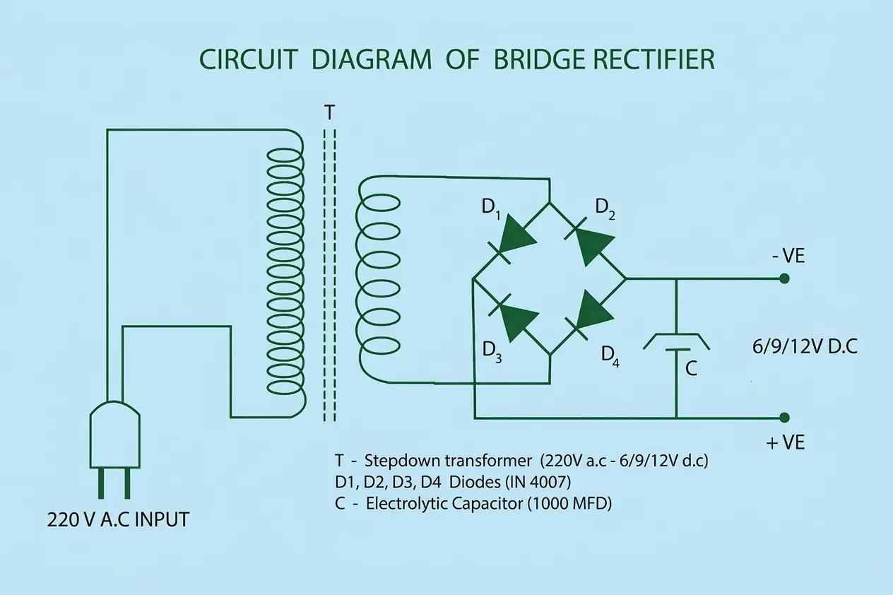
The Four-Diode Bridge Layout
The classic bridge rectifier uses four diodes connected around the load. Two AC input terminals feed the bridge, and the output side provides positive and negative DC rails.
The important idea is not just the physical layout. It is the switching behavior of the diodes. Diodes conduct only when forward-biased, so the circuit automatically routes current through the correct pair during each half-cycle.
| Component | Role in the Circuit |
|---|---|
| D1 and D2 | Conduct during one half of the AC cycle |
| D3 and D4 | Conduct during the opposite half of the AC cycle |
| AC input terminals | Supply alternating polarity to the bridge |
| Load | Receives current in one direction during both half-cycles |
Because the load current remains in the same direction, the output becomes pulsating DC rather than alternating current.
Step 1: What Happens During the Positive Half-Cycle
During the positive half-cycle, one AC terminal becomes positive relative to the other. In this condition, one pair of diodes becomes forward-biased and the other pair becomes reverse-biased.
The conducting pair allows current to pass through the load. The blocking pair prevents reverse flow. The result is that current crosses the load in the intended DC direction.
| Positive Half-Cycle Condition | Circuit Response |
|---|---|
| Upper AC side is positive relative to lower side | One diagonal pair of diodes conducts |
| Other diode pair is reverse-biased | Reverse path is blocked |
| Current crosses the load | Load sees forward current |
This is the first half of full-wave rectification. The circuit has taken one half of the AC waveform and turned it into usable output current.
Step 2: What Happens During the Negative Half-Cycle
When the AC source reverses polarity, the diode behavior also changes. The pair that previously conducted now blocks, and the other pair turns on.
That sounds like a reversal, but the load still sees current in the same direction as before. This is the central advantage of the bridge topology.
| Negative Half-Cycle Condition | Circuit Response |
|---|---|
| Lower AC side is now positive relative to upper side | The opposite diagonal pair of diodes conducts |
| First conducting pair turns off | Reverse current is blocked |
| Current still crosses the load in the same direction | Output remains unidirectional |
This means both halves of the AC waveform now contribute to the DC output. That is why the bridge rectifier is considered a full-wave rectifier.
Step 3: Why the Output Is Still Not Perfect DC
After rectification, the voltage no longer alternates above and below zero, but it is still not smooth. It rises and falls in pulses that follow the incoming AC waveform. This is called pulsating DC.
For many real systems, pulsating DC alone is not good enough. Sensitive electronics, battery systems, and power conversion stages usually need a more stable supply. That is why the rectifier stage is often followed by filtering and regulation.
| Output Stage | Electrical Condition | Practical Result |
|---|---|---|
| Immediately after rectification | Pulsating DC with ripple | Acceptable for some loads, inadequate for many electronics |
| After smoothing capacitor | Ripple is reduced | More stable DC bus |
| After further regulation or conversion | Voltage is shaped to the target requirement | Suitable for control boards, converters, or charging stages |
PandaExo’s article on calculating the smoothing capacitor value for a rectifier circuit is a useful next step if your goal is to understand how the rectified waveform becomes cleaner DC.
Why a Bridge Rectifier Is Commonly Preferred
Engineers choose the bridge configuration because it balances efficiency, practicality, and transformer requirements better than many simpler alternatives.
| Rectifier Type | Diode Count | Transformer Requirement | Relative Efficiency | Typical Use Case |
|---|---|---|---|---|
| Half-wave rectifier | 1 | Standard | Low | Very simple, low-power circuits |
| Center-tapped full-wave rectifier | 2 | Center-tapped transformer | High | Legacy power designs or special transformer architectures |
| Bridge rectifier | 4 | Standard | High | Modern power supplies, charger subsystems, industrial electronics |
The bridge rectifier uses more diodes than a center-tapped full-wave design, but it avoids the need for a specialized center-tapped transformer. In many commercial designs, that tradeoff makes the bridge topology more practical and more scalable.
Where Bridge Rectifiers Fit Into EV Charging Systems
In EV infrastructure, bridge rectification appears in more than one place. The exact role depends on charger architecture, power level, and subsystem design.
| EV Charging Context | How Rectification Is Used | Why It Matters |
|---|---|---|
| Internal charger control electronics | AC is rectified to power displays, controllers, and communication boards | Supports smart charger functions and system stability |
| AC charging hardware | Auxiliary power sections rely on rectified input for internal electronics | Keeps wallboxes and smart AC chargers operational |
| DC fast charging systems | Rectification is part of the front-end power path before downstream conversion | Enables high-power AC-to-DC energy processing |
| Power semiconductor modules | Rectifier reliability influences heat, ripple, and electrical stress | Directly affects uptime and maintenance cost |
That is why rectification remains important even when the broader conversation shifts to high-power DC charging or smart AC charging deployments. The conversion path may differ by charger class, but reliable rectification still underpins the system.
The Operational Issues Engineers Watch Closely
Once the theory is clear, the next concern is performance under real conditions. In field systems, the bridge rectifier is not judged by circuit elegance. It is judged by reliability.
Engineers typically watch for:
- Excessive forward voltage losses that reduce efficiency
- Heat buildup caused by current loading or weak thermal paths
- Ripple levels that place extra stress on capacitors and downstream converters
- Mechanical connection quality at terminals and busbars
- Component selection issues in harsh outdoor or commercial environments
These factors matter because a rectifier problem rarely stays local. Poor rectification can cascade into nuisance faults, shortened component life, and unstable charger behavior.
If your focus is failure analysis rather than circuit basics, PandaExo’s article on troubleshooting a 3-phase uncontrolled bridge rectifier in EV infrastructure goes deeper into diagnostic workflow.
Why Rectifier Quality Matters in Commercial Charging
Commercial EV charging equipment is expected to run across demanding duty cycles, variable site conditions, and long service windows. In that environment, a bridge rectifier is not just a commodity part. It is a reliability decision.
Higher-quality rectification helps support:
- More stable electrical performance under load
- Better thermal behavior in dense power assemblies
- Lower risk of repeat failures and service calls
- Stronger long-term uptime for charging assets
This is one reason PandaExo emphasizes both charging infrastructure and power semiconductor capability. The combination matters for buyers who need a partner that understands not only charger deployment, but also the electrical foundation that keeps the equipment running.
Final Takeaway
A bridge rectifier circuit works by using four diodes to steer both halves of an AC waveform through a load in the same direction. That simple idea makes full-wave rectification possible without a center-tapped transformer, which is why the bridge topology remains one of the most widely used circuits in modern power electronics.
For EV infrastructure teams, understanding this circuit helps explain how chargers convert incoming power, why ripple and thermal performance matter, and why component quality affects long-term uptime. If you are evaluating charger hardware or semiconductor components for dependable power conversion, explore PandaExo’s broader EV charger portfolio or contact the PandaExo team to discuss application-specific requirements.


